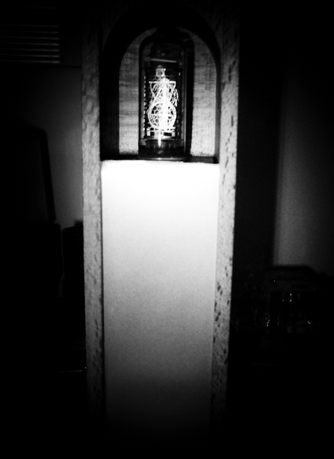
[still working after 8 years of continuous usage!]
[ In 2003 the global interest in nixie clocks was only beginning, and there were not so many of them commercially available, at crazy prices. B+ power supplies were usually done with transformers directly coupled with mains, a VERY dangerous things to do. Only for these reasons this project was justified and stimulating. Although the nixie clock engineering community is still a small one, nixie clock are now relatively common, there are dozens of sites and forums, with surprising designs; one of my favourites is the tubeclockdb forum ].
Everything started surfing the Internet looking for a cheap LCD display...
I am always been fascinated by computer history (being myself a relatively 'old' programmer), and I have been once more intrigued by some sites that referred to nixies as 'gas displays'. I remembered the old days where pinball machines (and big computers, but I never seen those) used this kind of numerical displays...
So I took a look on Ebay... and discovered that there was a growing interest in selling (and buying) Nixies. As it happens for tubes, some are (still now) highly overpriced, but outstanding quality and performance can be obtained at a low cost looking at the East Europe sellers. 'Made in USSR' Nixies are cheap, and beautiful...
In a hurry, I bought a whole bunch of them (dekatrons too)! Till now I used only some... but they do not have an expiry date (almost... there always may be a very small crack and/or hermetic seal leak allowing the atmosphere to slowly enter, during the years).
After a reasonable wait [shipping from Estonia or Lituania was (and maybe still is) not fast as in the USA or central Europe...] a complete ИН-xx Nixie set was in my hands. I had to decide which model was best suited for my first project...
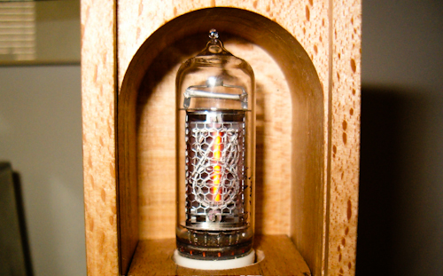
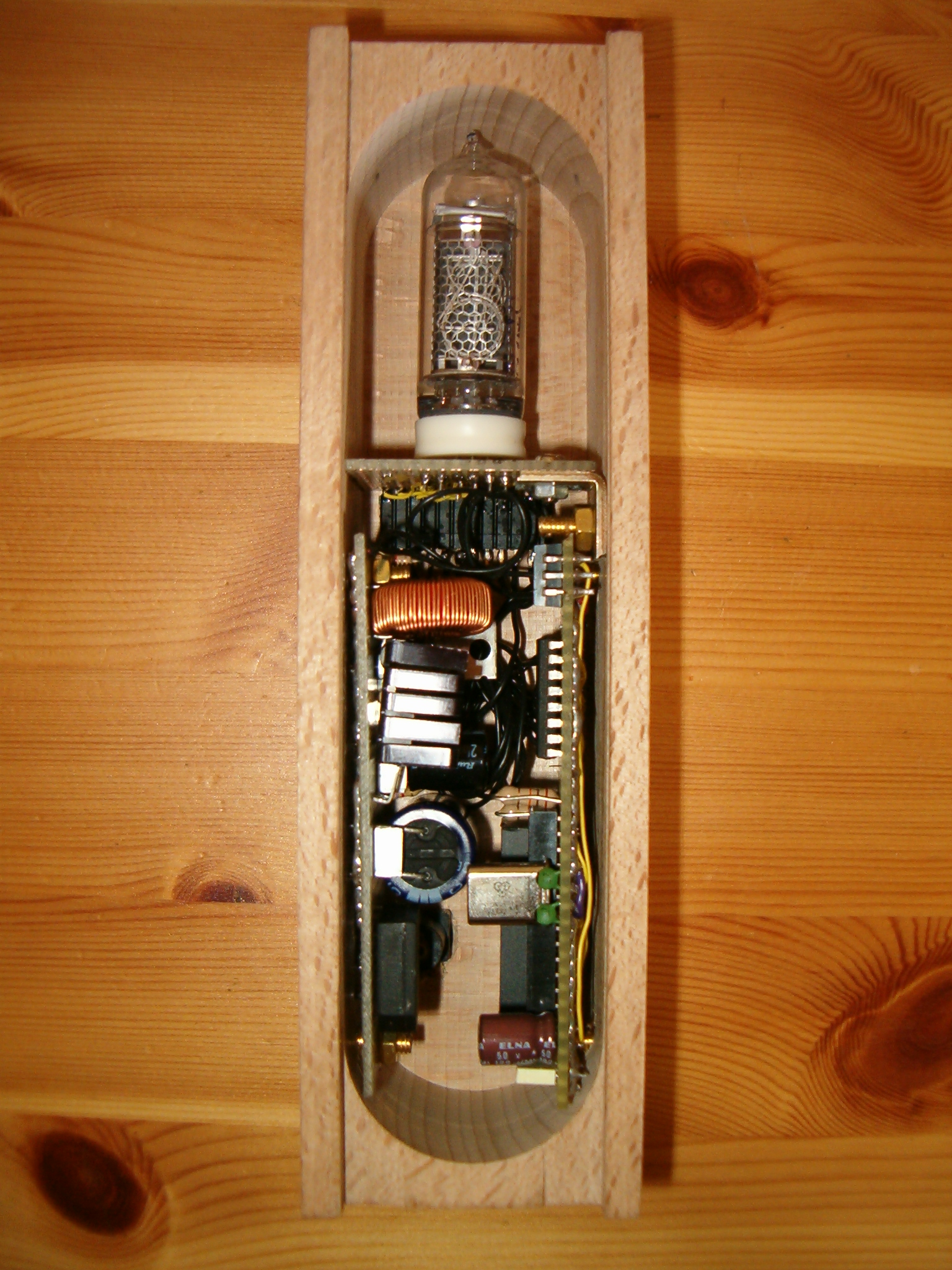
The choice has been done looking for a suitable container for my clock. I found a nice wooden box commonly available (it was the box of a commercial perfume, now long gone), and I started measuring... trying to imagine how compact and/or messy the prototype perfboard will be.
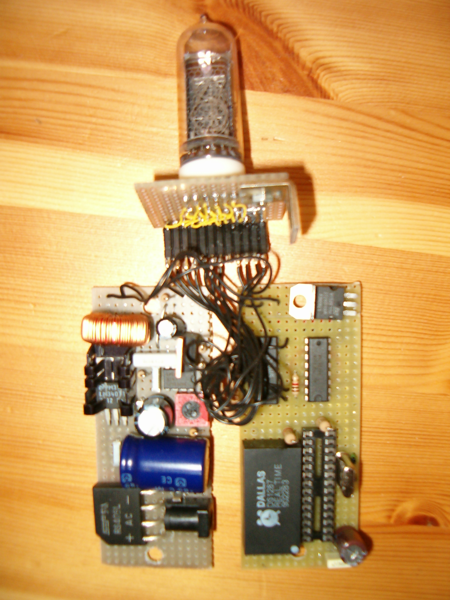
At the end I managed to keep the boards reasonably clean, compact and not (too) chaotic... separating the HV power supply from the logic, and assembling the whole as a 'sandwich'.
Giving the box dimensions, I used a ИН-14 Nixie.
I took a look over the Internet to find some ideas to obtain a safe 180V DC B+ from a wall-wart... with a couple of modifications to an existing step-up project (I don't remember the site where I found it, so I cannot add any credit...) I came up with this solution (120-180 variable DC output), based on the Motorola 34063 DC-DC converter application notes:
 (Original 2003 schematics)
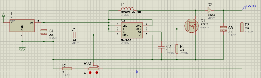 (revised schematics; I used it again later, in 2008)
The TO-220 heatsinks must be rated at 10-11 degrees centigrade per watt; current consumption under load after rectification is around 350mA.
The inductor (300uH) can be substituted with a 100uH one, to raise the output voltage to around 210-220V, but this would add 50mA to the overall current consumption. An higher output voltage is not reasonably obtainable with this kind of circuit.
The other components I used, (except diodes, capacitors, resistors, a scavenged 15V 1A AC transformer -to be rectified before providing power to the 7812!-, a fuse and holder on the transformer cable and the inductor) are:
-
an overkill RS405L silicon bridge rectifier I had laying around, instead of a basic 4-diodes bridge (it even requires a bit of drilling, because the leads are thicker than the perfboard holes...)
-
an IRF720 400V mosfet transistor
-
a BYV27 / 400 silicon diode rated 400V/2A
Not needing a lot of computing power but many outputs, I used a 4 Mhz Microchip PIC (16F873) as the heart of the system... with a reasonable quantity of C code to make everything run. It flashes the current HH:MM one digit at a time, with some delay between each pair of digits and a longer delay between each visualization. At midnight it 'exercises' every digit of the nixie, to prolong its life ('3' to '9' are less used, obviously).
( This is because if a cathode is illuminated, material is sputtered from this active cathode onto the glass envelope and the inactive cathodes.
In extreme cases at or near the end of tube life, the nixies darken with a gray or silvery coating on the inside of the glass. If a cathode is not used for a long time while others are lit, the coating on the inactive electrodes gets thicker and thicker. This coating is highly resistive, so if it gets thick enough, it prevents the inactive cathode from glowing. Then if the inactive cathode gets switched on, parts of it will be dimmer or totally dark.
Different nixies have different vulnerability to cathode poisoning, but normally it takes thousands of hours until it becomes a problem.
In "more recent" nixie tubes, a small amount of mercury is added to the tube's atmosphere. The mercury counteracts cathode poisoning but it also causes a slight tinge around the illuminating numerals or symbols. )
Having a junk PC motherboard at hand, I extracted an old DS1287 real-time clock to avoid errors caused by clock divisions on the PIC itself [there are precise time-correcting algorithms out there, but I did not think about it]; then I foresaw a 4-Nixie (or more) application, and decided to use a PCF8574 I2C remote I/O expander.
To avoid a myriad of transistors, I bought on Ebay a set of original K155ID1 Nixie drivers (DM7441A compatible; only one used here...)
Then I considered adding a light sensing device, and PWM support to make the nixie brighter during the day, and softer during the night... an OPT101 monolithic photodiode and a couple of 13007 high voltage-fast switching transistors. This feature has NOT been added on the final clock due to the lack of space in the wooden box, but has been extensively tested on a prototype board. HV has been therefore connected directly to pin 1 of the Nixie.
This is the result, compact and clean although on a perfboard instead of a PCB:
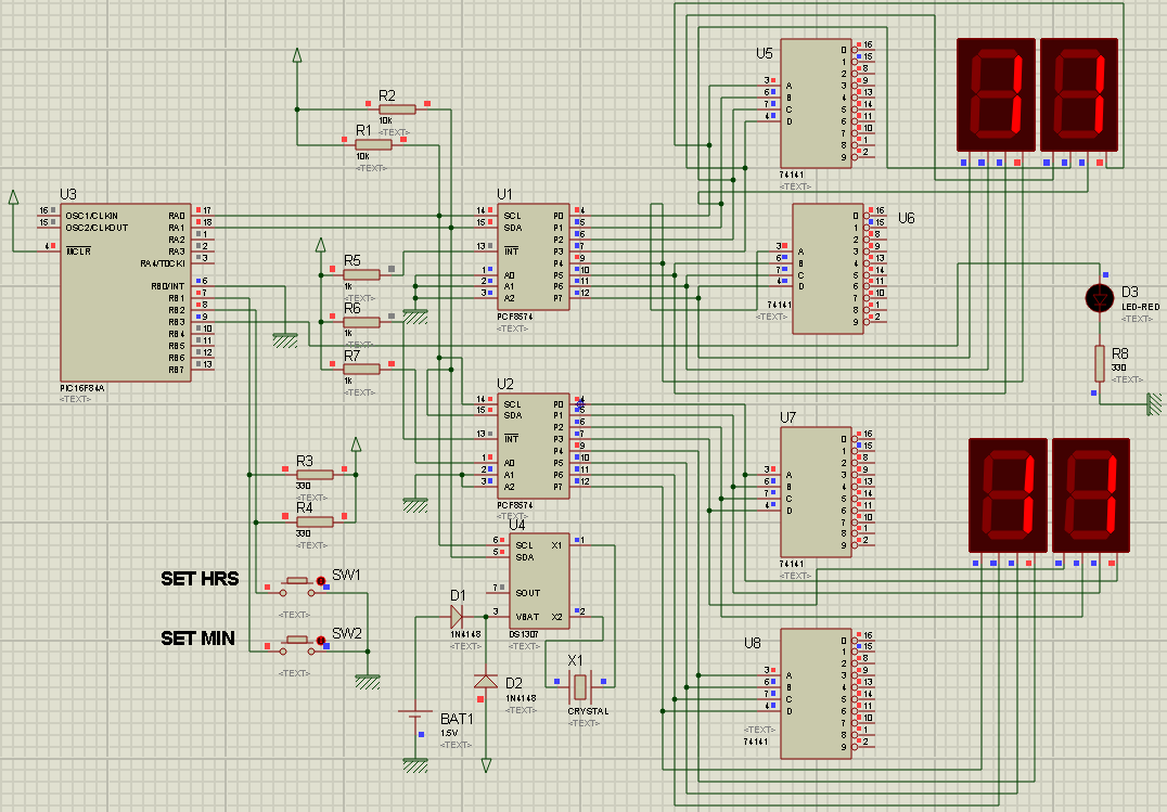
Of course the design is scalable... this is a later 'work in progress' one (2008) using I2C RTC and port expanders. A 4 (and more!) Nixies design with even a tiny 16F84A PIC is possible if using I2C (here the 74141 are still disconnected, and their inputs wired to intelligent 7-segments displays for an easy digital simulation and firmware debug in ISIS):
![]()

This work is licensed under a Creative Commons Attribution-Noncommercial-No Derivative Works 3.0 Unported License.